Picture the moment at the bench. You have a boardview open, you know the signal you want, and you can see every pin it touches. Then you look down at the real board and the only pin the net names sits on a chip with legs finer than a hair. Soldering onto it is a bad afternoon waiting to happen. The question that actually matters is not “what connects to what?” It is “where can I reach this without wrecking the board?”
A boardview, for anyone who has not met one, is a map of a circuit board: every component, every pin, and the invisible copper nets that wire them together. It is how repair technicians and hardware researchers find their way around a board they did not design. What an ordinary boardview viewer is less good at is the next step, turning “this net” into “this pad, right here, that I can get a probe onto.”
What it does
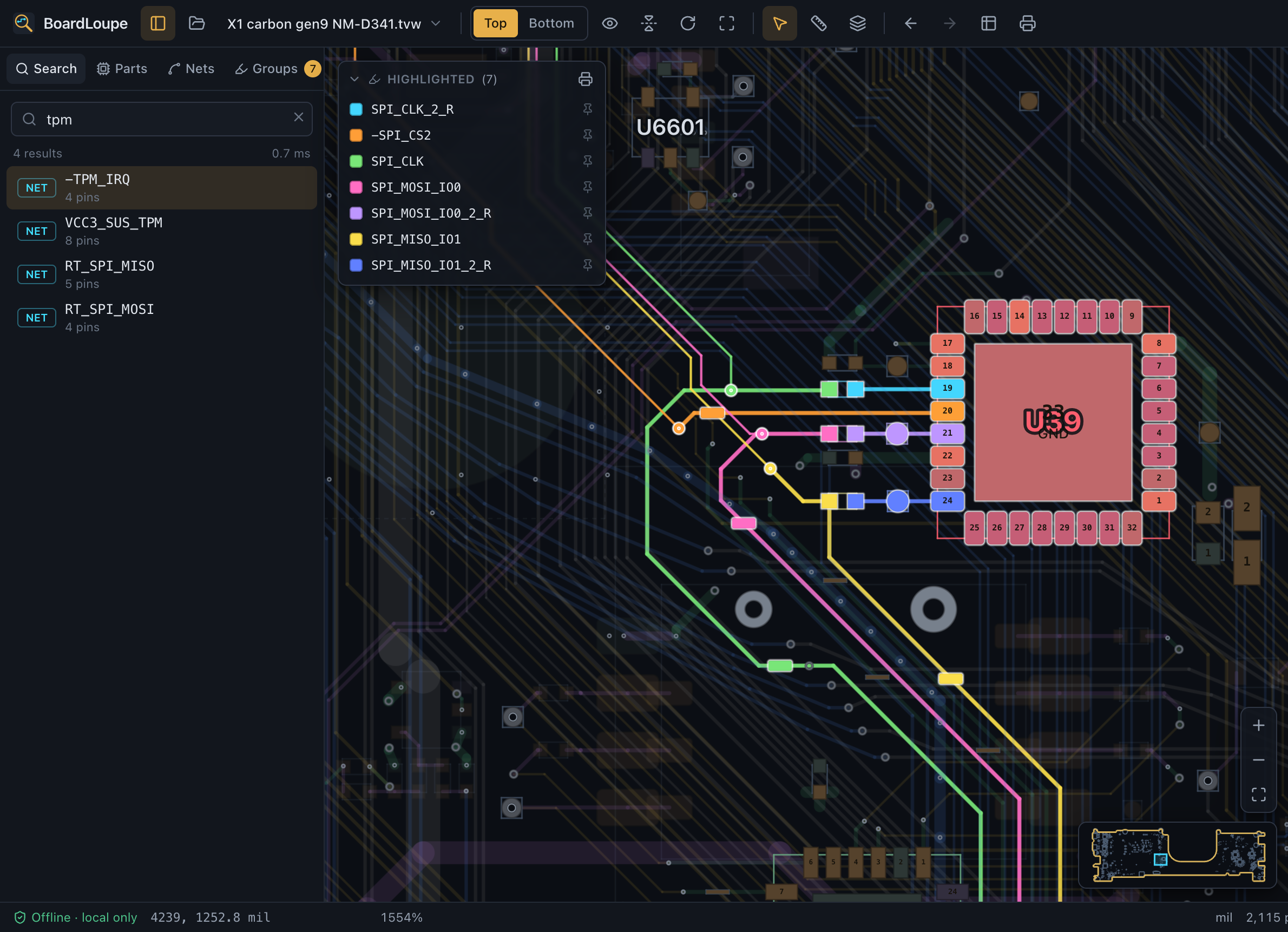
BoardLoupe is built for that step. You search for a component, a pin, or a net, and it highlights everything connected to it. You can then follow a signal as it passes through the small parts in its path, the series resistors, fuses and ferrite beads, and come out at a test point, a via, a connector, or simply a larger pad that is far kinder to a probe tip. The move is almost always the same: start at a pin you cannot reach, and walk the connection outward until you land somewhere you can.
The screenshots here follow a signal across a real laptop mainboard, a Lenovo X1 Carbon Gen 9 (board number NM-D341), which is exactly the kind of board we meet in class rather than a tidy demo part.
Two kinds of work, one feature
This helps two groups who do not always realize they are doing the same thing. A repair technician chasing a dead power rail has to move constantly between the idea of a signal and its physical spot on both faces of a packed board. The same tracing works for reset lines, clocks, and any other bus you need to find. For reverse engineering, you can light up several related nets together as one bus and see how it threads across the board.
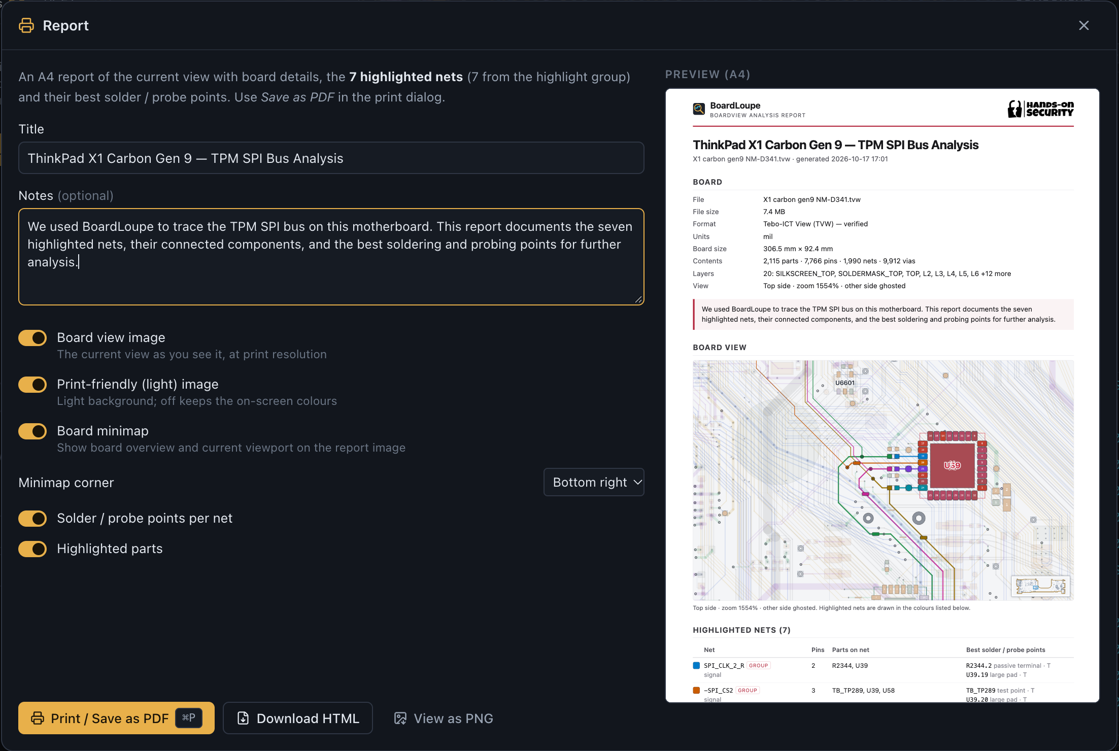
When you have found what you need, BoardLoupe’s reporting function exports a PDF of exactly what you highlighted, so the next person at the bench, or you next month, does not have to reconstruct it from memory.
Why this matters for our training
This is close to our own daily work, which is why we built it. In our hardware classes, the first real obstacle is rarely the theory of an attack. It is physical: finding a spot where you can safely clip onto a bus at all.
TPM sniffing is the example we keep returning to, and it is work we know well. On a machine with a discrete TPM, the chip talks to the rest of the system over a board-level bus such as LPC or SPI. We have long since stopped fighting the tiny TPM pins directly. Instead we look for accessible pads and follow a clock signal out through the series resistors in its path. That physical-mapping step is precisely what BoardLoupe is for: finding candidate points for each signal on the bus and seeing how they connect.
The limits matter as much as the capability. BoardLoupe only helps you find where to measure. You still need a logic analyzer to capture the traffic and separate protocol analysis to make sense of it. And a TPM on a board is not a vulnerability by itself. Whether any of this is exploitable depends on the specific hardware and how it is configured. For the background, the TPM platform specification and Microsoft’s BitLocker countermeasures are both worth reading.
TPM work is just the post we happened to write first. The same find-the-probe-point step shows up across a whole family of bus-sniffing targets we work on, and one of them recently came together on our bench. We will write that one up soon. Stay tuned.
Why we built it the way we did
We also had firm opinions about how a tool like this should feel to use. A student or a technician should be able to open a boardview without first standing up a Windows virtual machine or learning an unfamiliar legacy application. So BoardLoupe is a single HTML file that runs in the browser. There is nothing to install, nothing to download onto your machine, and it works offline.
Just as important, your boardview never leaves your computer. Nothing is uploaded. You are not handing a board that may be covered by an NDA to some online service you have no reason to trust. It is free and open source.
We will also be honest about how it was made. BoardLoupe was vibe-coded, put together quickly and by feel with an AI assistant rather than engineered to a formal spec. It does not set out to be the one perfect, do-everything tool, and for some specific jobs there are more capable or more polished options. That was never the point, and because the code is open, you do not have to take our word for any of it. What the tool does, it does well enough to save real time at the bench: less friction between spotting a signal and making a sound decision about where to measure it.
BoardLoupe is publicly available: Open BoardLoupe · Source code on GitHub · Short link